
Services
GPR Method
GPR works by sending a tiny pulse of energy into a material and recording the strength and the time required for the return of any reflected signal. A series of pulses over a single area make up what is called a scan. Reflections are produced whenever the energy pulse enters into a material with different electrical conduction properties or dielectric permittivity from the material it left. The strength, or amplitude, of the reflection is determined by the contrast in the dielectric constants and conductivities of the two materials. This means that a pulse which moves from dry sand (dielectric of 5) to wet sand (dielectric of 30) will produce a very strong reflection, while moving from dry sand (5) to limestone (7) will produce a relatively weak reflection.
While some of the GPR energy pulse is reflected back to the antenna, energy also keeps traveling through the material until it either dissipates (attenuates) or the GPR control unit has closed its time window (Figure 2). The rate of signal attenuation varies widely and is dependent on the properties of the material through which the pulse is passing.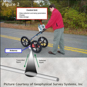 Materials with a high dielectric will slow the radar wave and it will not be able to penetrate as far. Materials with high conductivity will attenuate the signal rapidly. Water saturation dramatically raises the dielectric of a material, so a survey area should be carefully inspected for signs of water penetration.
Metals are considered to be a complete reflector and do not allow any amount of signal to pass through. Materials beneath a metal sheet, fine metal mesh, or pan decking will not be visible.
Radar energy is not emitted from the antenna in a straight line. It is emitted in a cone shape (Figure 2). The two-way travel time for energy at the leading edge of the cone is longer than for energy directly beneath the antenna. This is because that leading edge of the cone represents the hypotenuse of a right triangle.
Materials with a high dielectric will slow the radar wave and it will not be able to penetrate as far. Materials with high conductivity will attenuate the signal rapidly. Water saturation dramatically raises the dielectric of a material, so a survey area should be carefully inspected for signs of water penetration.
Metals are considered to be a complete reflector and do not allow any amount of signal to pass through. Materials beneath a metal sheet, fine metal mesh, or pan decking will not be visible.
Radar energy is not emitted from the antenna in a straight line. It is emitted in a cone shape (Figure 2). The two-way travel time for energy at the leading edge of the cone is longer than for energy directly beneath the antenna. This is because that leading edge of the cone represents the hypotenuse of a right triangle.
Because it takes longer for that energy to be received, it is recorded farther down in the profile. As the antenna is moved over a target, the distance between them decreases until the antenna is over the target and increases as the antenna is moved away. It is for this reason that a single target will appear in a data as a hyperbola, or inverted “U.” The target is actually at the peak amplitude of the positive wavelet (Bottom Figure 2). Data are collected in parallel transects and then placed together in their appropriate locations for computer processing in a specialized software program such as GSSI’s RADAN. The computer then produces a horizontal surface at a particular depth in the record. This is referred to as a depth slice, which allows operators to interpret a planview of the survey area.
Questions about Ground Penetrating Radar (GPR)
Is GPR a safe testing technique?
Many people question whether there is any danger for the person using GPR equipment, and the answer is no. Although “ground penetrating radar” may sound like a hazardous technique, it is extremely safe and emits roughly 1% of the power of a cellular phone signal.
Can I see non-metallic subsurface features with GPR?
 GPR is extremely accurate when it comes to locating metallic and non-metallic objects. GPR systems work by sending a tiny pulse of energy into the ground from an antenna. An integrated computer records the strength and time required for the return of reflected signals. Any subsurface variations, metallic or non-metallic, will cause signals to bounce back. When this occurs, all detected items are revealed on the computer screen in real-time as the GPR equipment moves along. Users can even tell from the signal returned whether the feature in question is metallic or non-me
How deep can GPR “see” to locate targets?
 Depth of GPR penetration depends on the material being surveyed and also upon the antenna frequency being used. For instance, GPR will penetrate ice, rock, soil and asphalt differently due to each material’s unique electrical properties. Lower frequency antennas will generally penetrate deeper, but there is a loss in resolution with the drop in frequency.
Soil conditions can vary greatly, which in turn affects GPR penetration. In general, dry sandy soils with little salt content return excellent survey resolution, but heavy clay-based soils are difficult to penetrate with GPR. In some situations, penetration depth may be limited to a few feet or less within clays, whereas pipes residing in sandy soils could be detected at depths up to 30 feet.
Your GSSI Application Specialist can help you find the equipment that is right for your project and profession.
Depth of GPR penetration depends on the material being surveyed and also upon the antenna frequency being used. For instance, GPR will penetrate ice, rock, soil and asphalt differently due to each material’s unique electrical properties. Lower frequency antennas will generally penetrate deeper, but there is a loss in resolution with the drop in frequency.
Soil conditions can vary greatly, which in turn affects GPR penetration. In general, dry sandy soils with little salt content return excellent survey resolution, but heavy clay-based soils are difficult to penetrate with GPR. In some situations, penetration depth may be limited to a few feet or less within clays, whereas pipes residing in sandy soils could be detected at depths up to 30 feet.
Your GSSI Application Specialist can help you find the equipment that is right for your project and profession.
Can GPR be utilized through water?
Yes. GPR can be utilized through fresh water, but it does not operate where salt water is present.
 Can GPR be used through ice?
Yes. GPR works extremely well through ice and snow. They are some of the most favorable conditions for GPR.
Can GPR be used with GPS?
Yes. GSSI’s systems can integrate with most GPS systems. The GPS position data files and GPR scans are automatically matched within our systems so that the resulting data shows proper GPS position.
Can GPR be used to map cemeteries?
Yes. GPR is the best geophysical technique for forensic victim location and for the mapping of graves in cemeteries. While we can sometimes image the body directly, GPR responds well to the disturbances in the soil which are created when a pit is dug and refilled.
Fault Locating
Buried cables do occasionally fail, for a variety of reasons and in many different ways.
Lightening strikes, overloads or surges, installation problems, shovel and rodent damage are
some of the common causes of damage that can lead to cable failure. Any discontinuity in the
cable jacket which allows moisture in over time corrodes the conductors. Cables fail either open circuit, short circuit or somewhere in between, to earth and/or to another conductor in the cable.
The type of fault should be determined as different faults require different approaches. A persistent fault to earth (a ground fault) is usually most accurately and most easily found with an A-frame. Open and short circuits are best found with a TDR, and a ‘flashing’ fault that only happens at high voltages usually requires a high voltage surge generator or ‘thumper’. Most transmitters in a fault finding system will have some way to indicate if there is a path to ground such as an ammeter or ohmmeter and some have both. If there is a path to earth, the a-frame is still one of the most popular and most recommended methods when the conductor is not enclosed in duct.


